DIY linkwitz-riley active crossover
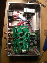
…OK so partially DIY. I got a pre-made PCB from ebay.
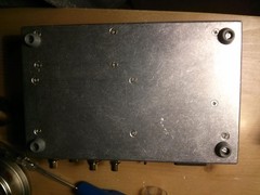
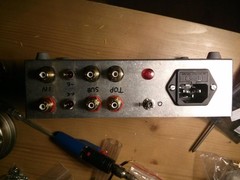
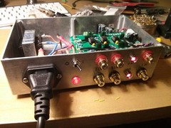
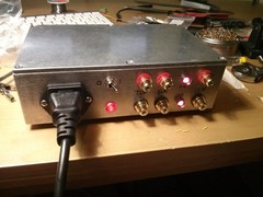
I based the project around a big die-cast aluminium box. To mark it, I used a centre punch, scribe and combination square. I later realised the box itself was not square, so my measurements were slightly off – no big deal, though.
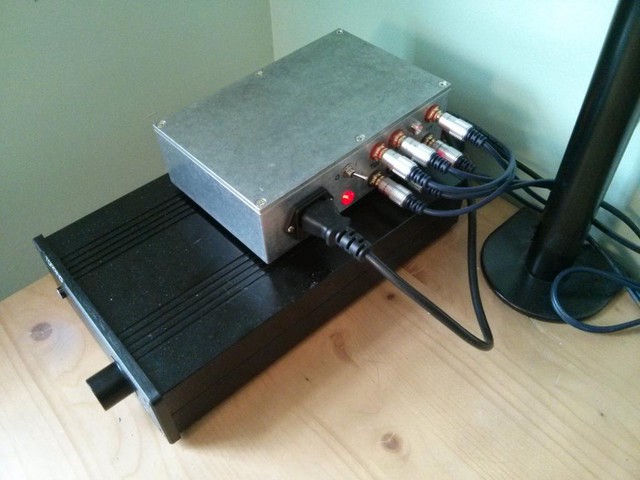
Anyway, it turned out well. Untested in the new form, yet – the bare boards work well though.
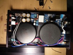
I used a few bridge rectifiers with a dual-pole transformer, big electrolytic caps with a couple of ceramic filters. LM7906 and LM7806 for + and - 6V rails, which is too much voltage for consumer line level operation – it results in some pretty bad transients on power on which could damage an amplifier. +/- 3V is probably better, with some kind of soft-start.
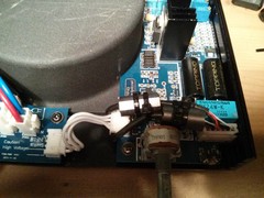
In a related note, the Topping TP60 amplifier I have was exhibiting quite a lot of RF interference though the speakers, presumably caused by USB traffic before and after the crossover. I added some ferrite beads in the signal path and the speaker output. It actually worked and the interference is quieter now, although still there.
There’s also a lot of transformer buzz.
Looking into it, the Topping TP60 measures quite badly according to Amir’s review at Audio Science Review. Given the noise issue, and the bad measurements, I can’t recommend the amplifier at all.
This amplifier, unfortunately, references everything to mains earth – the input signal, output and power supply. Worse, the signals and output go directly through the power supply. This flipping circuit board, Jen. Some chump has run the data lines right through the power supply. Amateur hour! I’ve got tears in my eyes!
Thanks for reading! If you have comments or like this article, please post or upvote it on Hacker news, Twitter, Hackaday, Lobste.rs, Reddit and/or LinkedIn.
Please email me with any corrections or feedback.
